Our paper has been accepted to the 2026 Conference on Precision Electromagnetic Measurements (CPEM 2026).
Abstract
Motivation
Helmholtz coils are commonly employed to generate uniform magnetic fields for the calibration of magnetic sensors and magnetometers. They are critical instruments for providing traceability for low magnetic field sensors and standards in the range from 0.1 mT to 20 mT. Calibrating a Helmholtz coil requires two tasks: (1) determining the coil constant, which relates the input current to the output magnetic field, and (2) evaluating the uniformity of the generated field within a specified working volume.
At KRISS (Korea Research Institute of Standards and Science), the uniformity evaluation is performed by scanning the working volume with a Hall sensor attached to a three-axis translation stage. However, conventional electrical actuators cannot be used for this scanning because they generate magnetic fields — some stepper motors produce fields in the range of tens of microteslas to over 100 µT — that would corrupt the measurement. This forces the operator to manually turn the mechanical knobs of the translation stage throughout the entire scanning process, making the calibration time-consuming (~90 minutes) and susceptible to human errors.
To address this limitation, we propose an automated scanning system using a custom-designed nonmagnetic pneumatic stepper motor. The motor operates solely on compressed air and is fabricated entirely from nonmagnetic materials, enabling precise sensor positioning without disturbing the magnetic field being measured.
Framework & System Design
The automated scanning system was designed to eliminate magnetic disturbances caused by conventional electric actuators in low-field magnetic measurements. The core of this system is a custom-designed pneumatic stepper motor driven by compressed air.
- Nonmagnetic Construction: The motor is fabricated using 3D-printed ABS and PLA components, plastic bearings (POM and Glass), and commercially available disposable syringes (3 mL) that serve as pressure chambers. All fasteners use nonmagnetic polymers (polyphenylene sulfide and polyamide MXD6).
- Operating Principle: The motor utilizes four pneumatic pistons arranged perpendicular to the axis of rotation. By applying sequential air pressure to these pistons, it executes a Lock-Push-Release mechanism to achieve bi-directional stepwise rotation of the geared axle. The step angle is 10°, defined by the axial misalignment between two nine-tooth gears.
- Performance: At 0.3 MPa input pressure, the motor generates 1.91 Nm of output torque — far exceeding the 6.6 mNm minimum required to move the translation stage. A full 360° rotation (nine 40° cycles) completes in 2.16 seconds, yielding approximately 27.3 RPM under short-tube conditions.
- Remote Control: The system is controlled by pneumatic regulators (SMC ITV0031-2BL) located at least three meters away from the measurement setup to prevent electrical interference. A LabVIEW program running on an NI USB-6001 DAQ module generates the sequential pressure signals for motor operation.
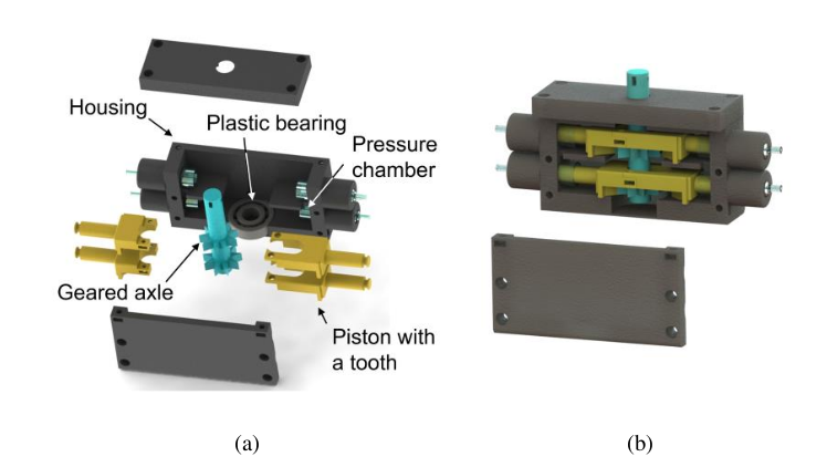
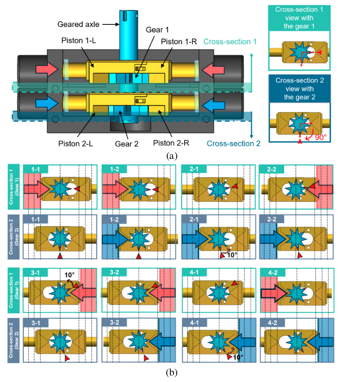
The motor's stepping mechanism is based on two sets of nine-tooth gears with a 10° rotational offset. When pressure is applied to a piston, it engages with one gear to latch and lock the axle. A subsequent piston then pushes the second gear, and when the first piston releases, the axle rotates by one step angle. This Lock-Push-Release sequence is repeated to produce continuous rotation, and reversing the step order reverses the rotation direction. Eight steps complete a 40° rotation, and nine such cycles produce a full 360° revolution. The use of commercial syringe barrels and rubber bulbs as pressure chambers and seals eliminated the need to re-engineer sealing components, significantly simplifying the fabrication process.
Experiments & Measurement Protocol
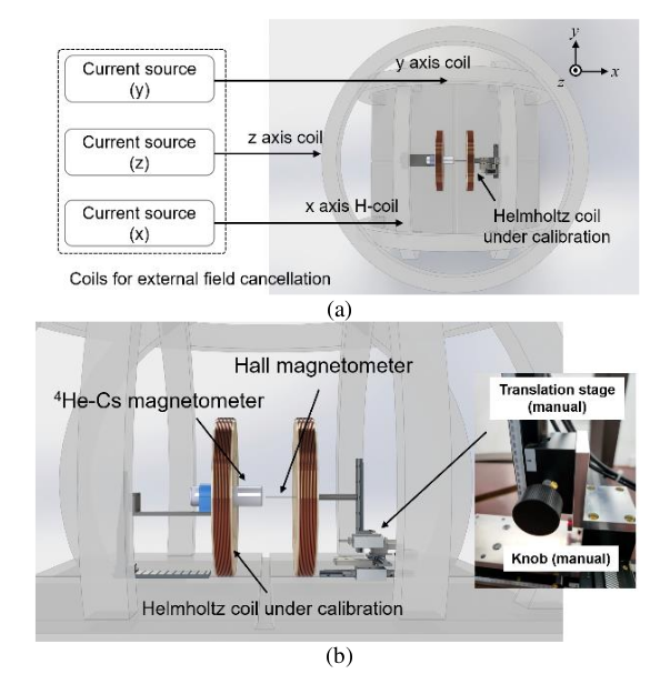
The proposed system was experimentally validated at the Korea Research Institute of Standards and Science (KRISS). All measurements were conducted inside a magnetically silent environment where three orthogonally aligned cancellation coils (approximately 2 m in diameter) suppress external magnetic interference, including the geomagnetic field, to below ±1 nT. The automated translation stage was attached to the Helmholtz coil calibration setup to map the working volume.
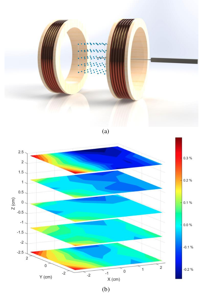
The scanning protocol involved calculating the Relative Deviation of the magnetic flux density (RDB) across a 3D grid using Equation (1):
RDB = (B(x, y, z) − Bcenter) / Bcenter × 100 %
The sensor automatically navigated 125 distinct positions (a 5 × 5 × 5 grid with 1.2 cm spacing) within the 4.8 × 4.8 × 4.8 cm³ working volume, measuring the spatial variation of the generated magnetic field relative to the center point. The magnetic flux density at the center was approximately 100 µT. A Hall sensor magnetometer (Lakeshore Cryotronics F71) with an RMS noise of 120 nT was used for field mapping. Because the system is automated, it enabled a higher number of sensor readings per point (20 instead of 5) without increasing the overall measurement time. The position accuracy was verified to be far less than 1 mm (the minimum scale of the stage rulers), and the accumulated position error after a full 125-point scan was also well below 1 mm.
Results
The automated scanning results were compared with the manual scanning baseline. The key findings are summarized below:
| Metric | Manual Scanning | Automatic Scanning |
|---|---|---|
| Field Uniformity | ±0.39% | ±0.43% |
| Measurement Uncertainty (k=2) | ±0.11% | ±0.06% |
| RDB Uncertainty (k=2) | ±0.16% | ±0.09% |
| Total Scanning Time | ~90 min | ~50 min |
| Human Intervention Time | ~90 min | ~10 min |
The measured magnetic field uniformity was within ±0.43% for the automatic scan, compared to ±0.39% for manual scanning. The difference of only 0.04% is well within the measurement uncertainty of ±0.16% (k=2), confirming that the pneumatic motor introduced no measurable magnetic interference. The maximum RDB was observed at the same corner position (-2.4 cm, 2.4 cm, 2.4 cm) in both methods, and the spatial patterns of the 3D field maps were nearly identical.
In terms of time efficiency, the total scanning time was reduced from 90 minutes to 50 minutes (~44% reduction), while the required human intervention time decreased dramatically from 90 minutes to just 10 minutes (>80% reduction). Furthermore, the time saved by automation allowed for increasing the number of Hall sensor readings per measurement point from 5 to 20, which reduced the type A uncertainty from ±110 nT (±0.11%) to ±60 nT (±0.06%) — all without a significant increase in total scanning time. Three repeated full scanning cycles confirmed excellent repeatability, with all measurements agreeing within their respective uncertainties.